
Roofing & cladding
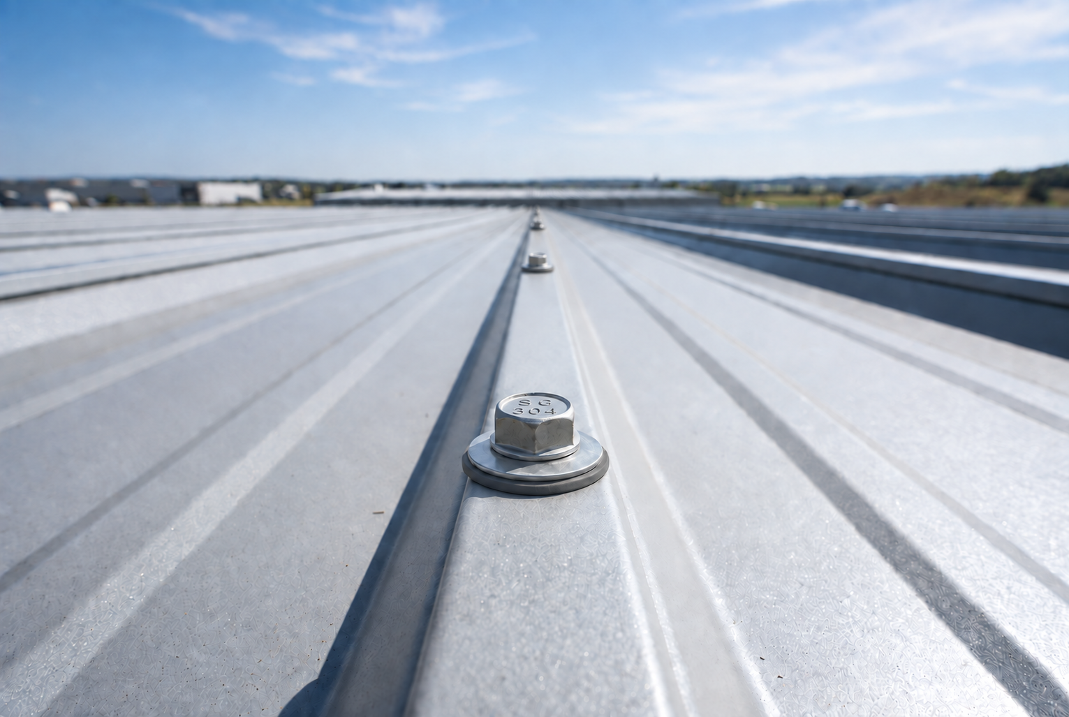
Metal sheets to steel supports. Consider support thickness, sheet profile and the required sealing assembly.
Hex head · Sealing washer where specified
STAINLESS STEEL · METAL FASTENING
Match the stainless construction, drill point and thread to the metal connection. Start with the supporting material and drilling range, then choose the head and sealing detail.
01 / APPLICATIONS
A roof sheet, a bracket and an insulated panel do not create the same fastening conditions.
Metal sheets to steel supports. Consider support thickness, sheet profile and the required sealing assembly.
Sheet-metal, enclosure and subframe connections. Match bearing area, access and drilling capability.
Account for panel depth, support thickness and the thread zones that position and clamp the assembly.
WHY THE MATERIAL MATTERS
Roofing, cladding and exposed metal connections need both corrosion resistance and reliable installation. The choice involves the screw body, drilling section, supporting metal and sealing detail—not simply stainless versus carbon steel.
Compare the grade and the protection system. Here, carbon steel includes both uncoated screws and screws protected by zinc or another coating. Their performance is not identical; compare the specified products in the actual service environment.
| Selection factor | Stainless steel screws | Carbon steel screws |
|---|---|---|
| How corrosion protection works[1][2] | Chromium in the alloy forms a thin passive film. It can reform after a surface scratch when oxygen is available; this does not repair lost metal or make every grade immune to corrosion. | Bare carbon steel has no equivalent chromium-rich film. Zinc plating, hot-dip galvanizing and other coatings add protection, but these are different systems with different exposure limits. |
| Wet service and salt exposure[3][4] | 304/305 and 316 offer different corrosion resistance. 316 generally resists chloride attack better, while trapped moisture, salt deposits and crevices still affect suitability. | Specify the actual coating, its thickness and the environment it is approved for. A generic description such as zinc plated or exterior screw is not enough for a demanding connection. |
| Damage during installation[1][7] | Corrosion resistance comes from the alloy, rather than only an applied barrier. Keep the surface clean and choose the grade for the conditions; a passive film cannot overcome an unsuitable environment. | Damage or wear can reduce the protection of a coating. Zinc can also protect sacrificially, so a small scratch does not mean immediate failure; the remaining coating and exposure both matter. |
| Strength and driving performance[5][2] | The alloy name is not a load rating. Check the exact screw's shear, withdrawal, pull-through and installation requirements. Stainless is not automatically a stronger substitute for a specified carbon-steel screw. | Heat-treated carbon-steel designs can provide high strength and a hard cutting point. Those benefits must be assessed separately from corrosion protection; verify the selected fastener and complete connection. |
| Maintenance and total project cost[6] | A suitable grade can reduce corrosion-related replacement needs. This matters where opening a finished assembly or gaining access costs more than the screws. Inspection and appropriate cleaning may still be needed. | A correctly specified coated screw can be a practical choice where exposure and maintenance suit the system. Compare purchase, installation, inspection and replacement costs, rather than assuming one material always costs less overall. |
Assess rain, condensation, salt and the compatibility of the screw, washer and sheet. A stainless body can address corrosion exposure, but weather sealing depends on the specified sealing washer, correct seating and the complete roof detail.
A bi-metal design combines an austenitic stainless body with a hardened carbon-steel drilling section. These parts serve different purposes. Confirm the joint construction, drilling range and environment for the exact model; the whole screw is not one uniform stainless alloy.
Check metal thickness, thread engagement and dissimilar-metal contact. A hardenable 410 screw is another possible construction, with different corrosion behaviour from 304/316. Panel depth and support-thread position also matter when fixing insulated assemblies.
These references explain general material behaviour. Confirm application suitability and performance for the selected StainGrip screw and connection.
02 / HOW TO CHOOSE
Work through four decisions, then compare the products that match.
Compare specificationsRecord the top sheet, supporting steel or aluminium, each thickness and any cavity.
Assembly depth sets grip needs; metal thickness, spacing between layers and drill-point geometry together determine suitability.
Compare a specified 410 design with a 304/316 body and hardened steel drill tip in a bi-metal design.
Bi-metal combines two material roles. The corrosion-resistant body and hardened drilling section are not the same material.
Confirm the model, point designation, steel grade and support thickness.
The cutting section must suit the material, clear chips and complete drilling before thread engagement causes binding.
Choose the bearing shape, verify any EPDM assembly and follow model-specific speed and tool guidance.
A hex flange is not automatically a watertight washer, and excessive speed or pressure can compromise installation.
03 / HEAD · DRIVE · POINT · THREAD
Treat cutting, thread engagement, head seating and weather sealing as separate selection decisions.
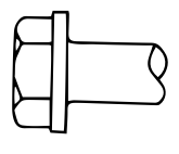
An external hex drive with an integral bearing flange. Use a matching nut setter; a weather seal needs a specified sealing assembly.
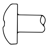
A raised head with a flat bearing underside for suitable sheet-metal and bracket connections.
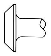
A broad, low-profile bearing shape. Check the available space, bearing diameter and attachment detail.
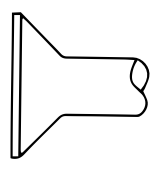
A tapered seat for a flush connection. Match it to a suitable countersink or prepared upper member.
Compare the bearing surface, visible finish and the prepared seat.
| Feature | How it works | Selection and product fit |
|---|---|---|
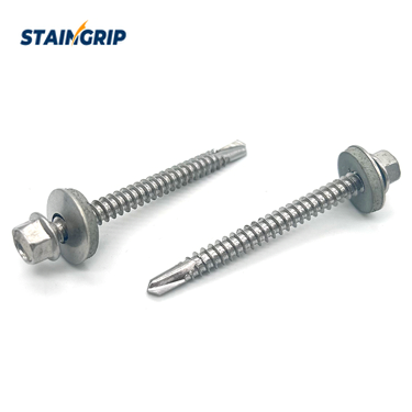
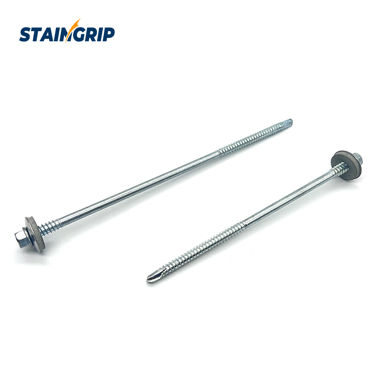
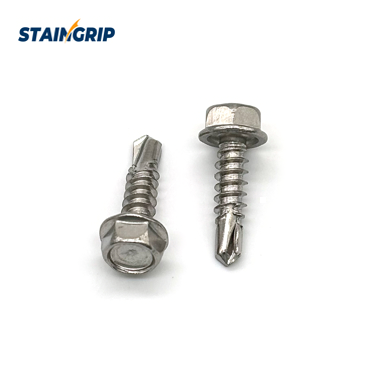
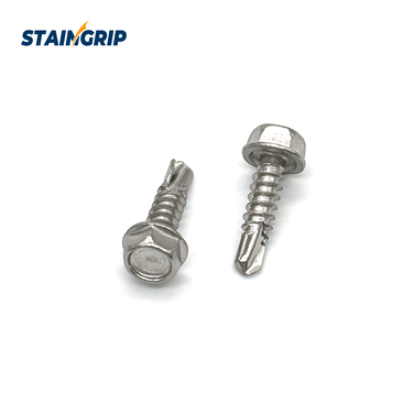
| Hex washer head and sealing assembly | The external hex transfers drive through a nut setter, while the flange provides bearing. Weather sealing depends on the specified washer system and installation. | Bi-Metal Hex Head Self-Drilling Screws lists a stainless washer with bonded EPDM. Confirm washer size, sheet profile, compression and environment; a bare metal washer is not an equivalent weather seal. |
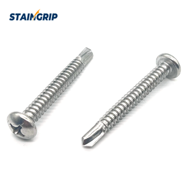
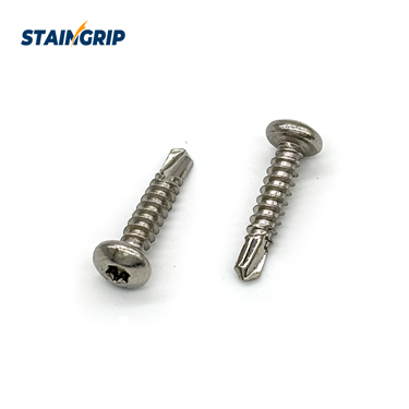
| Pan head | A raised head with a flat underside seats against a compatible sheet or fitting. The drive recess and bearing face perform separate functions. | Use a suitable flat seat and sufficient driver clearance. Bi-Metal Pan Head Screws lists pan-head bi-metal constructions; match the ordered point and drive to the connection. |
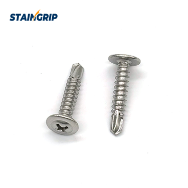
| Wafer head | A wide, shallow head offers a relatively low-profile bearing surface. Check the diameter and thickness where the fixing lies beneath another component. | Wafer Head Self-Drilling Screws is a listed wafer-head design. Confirm recess, material construction and drilling range; a broad head alone does not prove sheet pull-over resistance. |
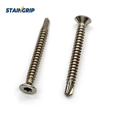
| Flat / countersunk head | A tapered underside requires a compatible recessed seat. It gives a flush finish only when the upper component and countersink match the head. | Flat Head Torx Self-Drilling Screws lists a Torx flat-head configuration. Check sheet thickness and the prepared seat; avoid forcing the head through a thin, unsupported surface. |
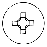
Use the correct Phillips bit for a specified recessed-head design. Keep the bit seated and follow the product’s driving guidance.
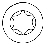
A six-lobe recess for a matching Torx bit. Confirm the recess size and driving conditions for the selected configuration.
Choose the recess and the matching bit as one specification.
| Feature | How it works | Selection and product fit |
|---|---|---|
| Torx / six-lobe — TX10–TX30 enquiry range | The six-lobe recess requires the matching bit size and full engagement. Head diameter and recess depth limit which drive can be specified. | TX10–TX30 is a range to discuss when enquiring, not a promise of every size. Selected deck products currently list T20 / T25. |
| Pozidriv — PZ1–PZ3 enquiry range | Pozi and Phillips have different recess geometries. Identify the recess from the ordered drawing and use a matching driver rather than treating them as interchangeable. | PZ1–PZ3 can be included in an enquiry. The current product comparison does not confirm this complete range or a Pozi version of every head. |
| Phillips — PH1–PH3 enquiry range | A Phillips recess needs a correctly sized cross-head bit, kept aligned while driving. The specified screw size does not by itself determine the bit size. | PH1–PH3 is an enquiry range. Phillips configurations appear in the catalogue, but the exact size and availability must be agreed for the chosen model. |
| Square — SQ1–SQ3 enquiry range | A square recess uses the matching square bit. Check recess size and driver fit before production installation, especially when working with a small trim head. | SQ1–SQ3 is an enquiry range; existing listings include #1 / #2 square options and Square Drive Flat Head Deck Screws specifies SQ2. Confirm each model rather than extending these entries. |
| External hex — nut setter | An external hex is driven around the outside of the head. Across-flats size is independent of the screw’s nominal thread diameter. | Specify the required nut setter size from the product drawing. Keep the tool square and control seating to avoid damaging the washer or sheet. |
TX10–TX30, PZ1–PZ3, PH1–PH3 and SQ1–SQ3 are bit-size ranges to discuss in an enquiry. Existing listings include T20 / T25 and #1 / #2 square options; confirm each ordered head and drive.
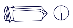
Compare the cutting section and flute geometry. Confirm the point material, support metal and drilling range for the exact screw.
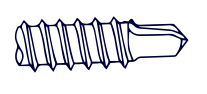
A smaller-diameter drilling section relative to the thread is a distinct configuration. Request the matching drawing and application data; do not substitute by appearance.
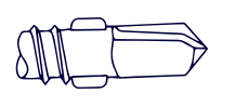
The wings form a separate feature behind the drill tip. Confirm the upper-material clearance, wing break-off and support requirements for the selected board-to-metal system.
Identify the receiving material before deciding whether a pilot or clearance hole is needed.
| Feature | How it works | Selection and product fit |
|---|---|---|
| Standard drill point / Tek 2 or Tek 3 | Fluted cutting geometry creates the hole for thread engagement. Point designation, flute length and point material all matter when selecting the drilling configuration. | Bi-Metal Pan Head Screws lists Tek 2 / Tek 3 options and Bi-Metal Hex Head Self-Drilling Screws lists Tek 3. Request the drilling range for the actual support and screw, not a generic designation alone. |
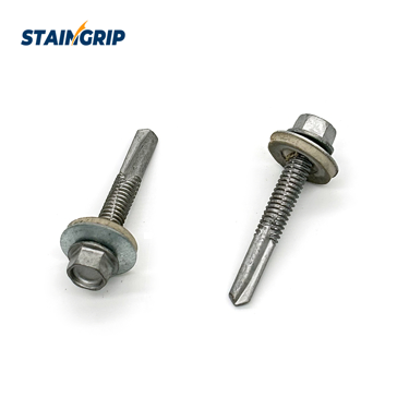
| Extended #5 drill point / Tek 5 | An extended cutting section provides a different drilling configuration. It is the point design, rather than overall screw length, that distinguishes this arrangement. | Bi-Metal #5 Point Self-Drilling Screws lists an extended #5 point. Confirm its rated steel thickness, steel grade, speed and build-up before selection; do not infer capacity from the illustration. |
| Reduced or winged drill point — enquiry reference | A reduced tip changes drilling diameter relative to the thread. A winged tip adds upper-material clearance features; these are different geometries with different installation requirements. | Submit the joint section and request the corresponding drawing and application data. Availability and suitability are configuration-specific, even when the head and material grade match. |
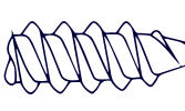
Compare the spacing of the thread crests. The exact pitch and engagement must suit the receiving metal and the chosen screw.
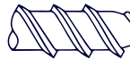
A wider-spaced profile is shown for comparison. Select from the product drawing and connection data; pitch alone does not establish drilling capacity or load performance.
Select the thread for the receiving material, and check where it engages within the joint.
| Feature | How it works | Selection and product fit |
|---|---|---|
| Pitch matched to the support | Thread pitch and profile control engagement with the receiving metal. A fine-looking thread is not, by itself, evidence of drilling capacity or connection strength. | Use the selected product drawing and test data for the support thickness and metal grade. Confirm the required fully formed thread engagement after drilling. |
| Full or partial thread | The threaded and unthreaded sections determine where the screw engages within the assembly. A suitable layout must accommodate the upper sheet, support and any gap. | Bi-Metal Hex Head Self-Drilling Screws lists full and partial arrangements. Specify the complete joint section and grip requirements; verify that the drill point clears before thread engagement binds the layers. |
| Upper support thread — sandwich panels | An additional upper thread supports the outer panel layer in a designed panel-fixing system. It works with the main support thread and sealing detail. | Sandwich Panel Screws lists an upper support thread. Confirm insulation thickness, sheet profile, support metal and installation depth, and request the corresponding panel connection data. |
These illustrations compare common screw geometries; they are not dimensioned product drawings. Confirm the exact head, drive, point and thread combination for the selected StainGrip product. Head & drive reference ↗ · Point & thread reference ↗
04 / MATERIAL & ENVIRONMENT
Compare stainless grades and coated carbon steel by corrosion behaviour, installation demands and the complete connection.
| Material / construction | Technical behaviour | Metal connection fit | Selection details |
|---|---|---|---|
| 304 stainless steel | An austenitic chromium-nickel steel commonly called 18/8. It balances general corrosion resistance and formability. Cold working can strengthen it; conventional heat treatment does not harden it like 410. | Used for stainless bodies in selected self-drilling constructions. For drilling into steel, specify the complete screw construction and point; the 304 grade alone does not establish drilling ability. | Assess 316 where salt or chemical exposure is more demanding. The 304 designation does not establish a load rating or automatically certify an A2-70 property class. |
| 305 stainless steel | Higher nickel content reduces work hardening compared with 304. Good ductility and cold-forming behaviour suit fastener manufacture, but do not guarantee that a finished screw cannot break during installation. | Primarily a forming and material-selection comparison here. No 305 self-drilling configuration is established by the products shown; a drill-capable construction must be specified separately. | Do not infer lower driving torque or freedom from head breakage from nickel content alone. Correct bit fit, pilot-hole requirements and controlled seating still matter. |
| 316 stainless steel | Molybdenum improves resistance to chloride-driven pitting compared with 304/305. This makes 316 worth assessing for salt exposure, while crevices, deposits and concentrated chemicals can still cause corrosion. | An option for selected stainless bodies in roofing and cladding fixings facing chloride exposure. Drill-tip construction, sealing washers and dissimilar-metal contact require separate checks. | Select by salt concentration, wetting, drainage and maintenance access. Distance from the coast alone is insufficient; 316 is neither a universal marine approval nor a lifetime guarantee. |
| 410 hardened stainless steel | A magnetic martensitic grade that can be hardened by heat treatment. Hardness supports cutting and driving functions, but its corrosion resistance is lower than 304/305 or 316. | A one-piece hardenable option for drilling and tapping within the selected screw’s tested range. Check metal thickness, installation speed, driving torque and any protective coating. | Use product data for torque and strength rather than a generic high-torque claim. Review the exposure and finish carefully; hardened construction does not confer 300-series corrosion resistance. |
| Coated carbon steel | Heat-treated designs can offer high strength and a lower purchase cost. Corrosion performance depends on the specified coating system; zinc plating, galvanizing and proprietary multilayer finishes are not interchangeable. | A practical option for selected metal connections where the coating and service conditions are matched. The hardened point, required corrosion protection and any roof sealing detail must work together. | Coating damage can reduce protection, although zinc can protect small exposed areas sacrificially. Compare installation, inspection and replacement costs as well as the initial screw price. |
| Bi-metal construction | Combines an austenitic stainless body with a hardened carbon-steel drilling section. The body addresses corrosion exposure while the harder tip and lead threads provide the cutting function. | For selected roofing, cladding, panel and metal-frame connections requiring stainless body corrosion resistance and steel-drilling capability. Choose the exact body grade, point length and support-thickness range. | Check where the hardened section finishes relative to the joint and specify the washer where sealing is needed. Bi-metal does not mean the entire fastener is stainless steel. |
Choose appearance, driving lubrication and corrosion protection as separate requirements. Confirm the finish on the exact screw you order.
| Finish / treatment | Purpose and application | How to specify |
|---|---|---|
| Plain / uncoated stainless | A metallic stainless surface without an added decorative or barrier coating. Corrosion selection still starts with the alloy and exposure. | Request the required surface condition on the drawing. Plain appearance alone does not specify cleaning or passivation. |
| Passivation | A controlled surface treatment used to remove free-iron contamination and support a clean passive stainless surface; it is not a paint layer. | Listed as a finish request for wood and deck ranges. Agree the process, cleanliness checks and inspection documents. |
| Painted heads | Teak, Charcoal, Cedar, Sand and White are listed examples on selected deck designs. Other colour matching can be reviewed against a sample. | Colour availability is model-specific. Confirm board reference, shade, gloss, coverage and the protective system separately. |
| Wax / lubricating finish | A specified lubricant can reduce friction during driving. Treat lubrication as an installation feature, not a substitute for a suitable corrosion-resistant alloy or coating. | Wax is a custom enquiry item, not a stated standard finish for these models. Agree coating compatibility and installation requirements before production. |
| Ruspert / protective coating | Ruspert is listed as an optional finish on selected self-drilling screws. Selected 410 deck designs list exterior protection without a universal coating system. | Specify the screw material, coating system and exposure. For a 1000-hour ASTM B117 requirement, agree the sample, acceptance criteria and test report; no family-wide 1000-hour rating is implied. |
Salt-spray hours describe a specified laboratory test. They do not by themselves predict service life outdoors. Match the coating, base metal, treated timber and neighbouring metals to the actual connection.
Drilling thickness, load values and installation settings are specific to the selected screw and substrate. Request the matching technical data.
BEFORE YOU SPECIFY
Not necessarily. Length provides reach through the assembly. Drilling ability depends on the point geometry, cutting material, support metal and installation conditions.
No. These designs combine a stainless steel head/body with a hardened carbon-steel drilling section. Confirm the precise construction and finish for your application.
A Type 17 point is designed for wood entry and chip clearance. For steel supports, select the appropriate metal-drilling point and thread with a verified drilling range.
05 / SPECIFICATION COMPARISON
Review 9 relevant designs in the StainGrip range. Follow a product name for its full details.
Use these catalogue options to prepare your enquiry. Confirm the exact diameter × length × material combination, drilling capacity and drawing before ordering; listed options do not guarantee that every combination is available.
Compare all 9 fields · Swipe or scroll the table →
| Product design | Material | Diameter | Length | Head | Drive | Point / drill tip | Thread | Finish / Colour |
|---|---|---|---|---|---|---|---|---|
| Bi-Metal Pan Head Screws | 304 / 316 body + hardened steel tip | #8, #10, #12 and #14 | ½–8 in (13–203 mm) | Pan | Phillips / Torx; confirm | Bi-metal Tek 2 / 3 | Specify thread layout | Ruspert; other barrier finishes reviewed by enquiry |
| Bi-Metal Hex Head Self-Drilling Screws | 304 / 316 body + hardened steel tip | #8, #10, #12 and #14 | ½–8 in (13–203 mm) | Hex washer | External hex | Bi-metal Tek 3 / 5 | Full / partial / support options | Ruspert coating; project-specific finishes by enquiry |
| Sandwich Panel Screws | 304 / 316; solid or bi-metal configuration | #8, #10, #12 and #14 | ½–8 in (13–203 mm) | Hex washer | External hex | Self-drilling; Tek 3 / 5 options | Upper support thread and lower fastening thread | Ruspert coating by configuration enquiry |
| Bi-Metal #5 Point Self-Drilling Screws | 304 / 316 body + hardened steel tip | #8, #10, #12 and #14 | ½–8 in (13–203 mm) | Hex / wafer / flat; confirm | External hex (pictured) | Extended #5 / Tek 5 | Specify engagement | Ruspert / silver barrier coating / zinc-plated options |
| Pan Head Torx Self-Drilling Screws | 410 / 304 / 316; verify construction for substrate | #8, #10, #12 and #14 | ½–8 in (13–203 mm) | Pan | Torx / star drive | Self-drilling Tek point | Full tapping thread | Ruspert coating by configuration enquiry |
| Wafer Head Self-Drilling Screws | 410 / 304 / 316; verify construction for substrate | #8, #10, #12 and #14 | ½–8 in (13–203 mm) | Wafer / flange | Phillips cross recess | Self-drilling Tek point | Full tapping thread | Ruspert coating by configuration enquiry |
| Flat Head Torx Self-Drilling Screws | 410 / 304 / 316; verify construction for substrate | #8, #10, #12 and #14 | ½–8 in (13–203 mm) | Countersunk flat head | Torx / star drive | Self-drilling Tek point | Full tapping thread | Ruspert coating by configuration enquiry |
| #10 x 1 in Self-Drilling Screws | 410 / 304 / 316; verify construction for substrate | #10 | 1 in (nominal 25 mm) | Indented hex washer | External hex | Self-drilling Tek point | Full tapping thread | Ruspert coating for an agreed material and size combination |
| #8 x 1 in Self-Drilling Screws | 410 / 304 / 316; verify construction for substrate | #8 | 1 in (nominal 25 mm) | Indented hex washer | External hex | Self-drilling Tek point | Full tapping thread | Ruspert coating for an agreed material and size combination |
Scroll horizontally to compare all specification fields. Inch ranges are nominal catalogue ranges; approve final dimensions and units on the quotation.
Use the product rows above for listed model options. Wider dimensions and alternative drives can be submitted for a quotation and feasibility review.
| Parameter | Listed product scope | Custom enquiry scope |
|---|---|---|
| Diameter | Many series list #8, #10, #12 and #14; dedicated #8 and #10 products also have individual specifications. | Extended enquiry: #6–#15 or an exact metric major diameter within 3.5–8.0 mm. Check the head, drilling tip and thread as a complete design. |
| Length | Many series list ½–8 in (approximately 13–203 mm). The dedicated #8 and #10 products shown are 1 in long. | Extended enquiry: up to 9 in, with a specified metric dimension if required. A 12–228 mm brief or 410 length of ¾–9 in or an exact metric length within 20–228 mm needs a model-specific quotation. |
| Material / construction | 304 / 316 bi-metal body options and selected solid stainless or 410 constructions; see each product row. | Do not select drilling performance by grade alone. Specify support metal, hardness, total drilling thickness, flute length and usable thread engagement. |
| Drive recess | External hex, Phillips and Torx are listed by model. | If requesting TX10–TX30, PH1–PH3, PZ1–PZ3 or SQ1–SQ3, identify the exact recess and head in the custom brief. Pozi and Square availability is subject to design review. |
Extended ranges are quotation requests, not catalogue availability or interchangeable inch/metric conversions. The accepted drawing and quotation define the manufactured size, tolerances, grade and finish.
Compare drill-point designs, head shapes and bi-metal construction.
EXPLORE OTHER FASTENING SOLUTIONS
START A CONVERSATION
Tell us the screw design, material, dimensions and finish you need.
Our technical engineers will contact you within one business day.