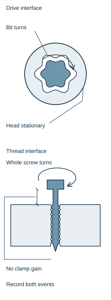
Record whether the bit slips inside the head or the whole screw turns without clamping. Keep the failed screw, mating part and bit together for a controlled comparison.
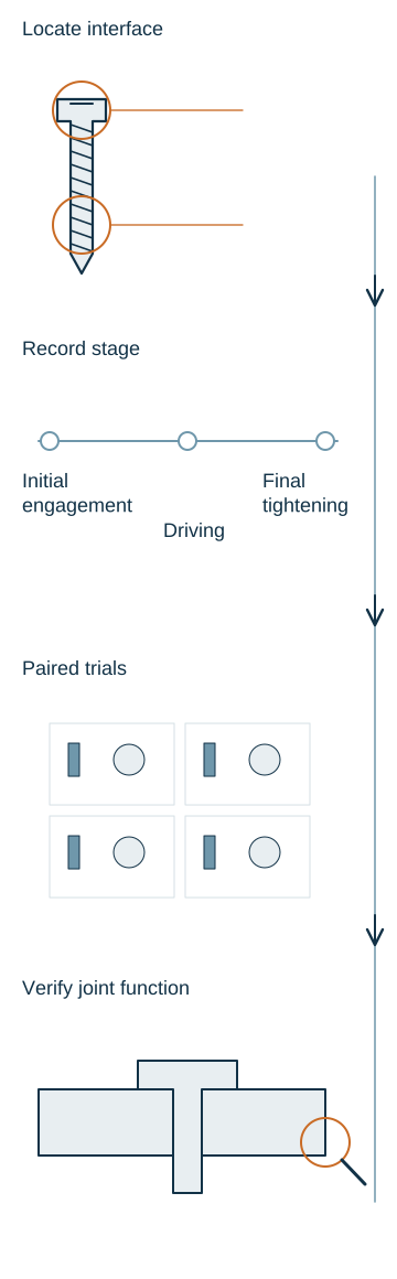
Locate the failed interface
Swipe the table sideways to compare every column. Keyboard: use the left and right arrow keys.
| Review item | What to check and how to interpret it |
|---|---|
| Bit rotates inside the head | A bit that rotates or jumps inside a stationary head points the investigation toward the drive surfaces. |
| Whole screw rotates without clamp force | A whole screw that turns without developing clamp force instead makes the external and internal threads relevant. |
| Both events occur | Both events belong in the record when they occur together. |
| Diagnostic record | Photographs of the recess before and after a controlled trial, together with the screw’s rotation and seating state, provide more diagnostic information than a complaint described only as slipping. |
Map the damage to the assembly stage
Record when confirmed recess damage begins. Early damage calls for checks of entrance impacts, contact at the upper edges, incomplete insertion and misalignment. Damage during final tightening also calls for review of torque demand and tool shutoff behavior. Contact profile and tool matching affect torque transmission, but proprietary drive-system performance claims cannot be assigned to every six-lobed screw.
A useful production-complaint record links the affected lot and operation count to the number of damaged drives, tool identification and exact change date. Together, these records help distinguish a batch-related shift from progressive bit wear. They also provide a stronger basis for approving a correction than isolated photographs alone.
Separate stainless material response from added driving resistance
The timing must be interpreted alongside both drive capacity and driving resistance. A 304 or 316 screw should not be rejected simply because stainless is described as soft. Finished drive performance depends on local geometry and the material condition produced by manufacturing. Austenitic grades can be strengthened by cold working; 410 can follow a hardening and tempering route. Those processes do not make different grades interchangeable. Questions about material condition need evidence from applicable finished-product requirements and test locations. An arbitrary surface indentation compared with a raw-material brochure does not provide that evidence.
In a stainless machine-screw assembly, a sound recess can be damaged because the thread pair begins to gall. The tool then demands more torque without producing normal rundown. A retained mating component allows examination of both sides of the pair; intact external appearance does not rule out internal adhesive damage. For a tapping or drilling screw, the investigation instead needs to locate resistance within the penetration or thread-creation stages. The same damaged head can therefore be the outcome of different problems downstream of the drive.
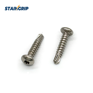
The pan-head Torx self-drilling screw is a relevant design when the investigation must separate penetration, thread creation and seating. Confirm its exact material option, point construction and intended receiving material for the order; its product listing does not establish performance in an untested sheet stack.
Separate tool and screw effects with paired trials
Swipe the table sideways to compare every column. Keyboard: use the left and right arrow keys.
| Review item | What to check and how to interpret it |
|---|---|
| Trial purpose | Controlled paired trials can separate these possible causes. |
| Controlled comparison | Such a trial combines accepted and suspect screws with identified new and used bits under the same joint conditions, with insertion depth, alignment, axial pressure, program and damage location recorded for each combination. |
| Damage follows the tool | Damage that follows a tool points toward its size or wear. |
| Damage follows the screw lot | Damage that follows a screw lot directs attention to the finished recess and surrounding material. |
| Traceability and variable control | Traceability between combinations and results is essential to that interpretation; simultaneous changes to the bit, lubricant and torque make the source of improvement difficult to identify. |
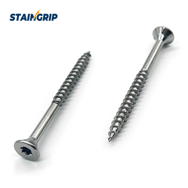
For board-to-joist work, the deck-screw application information and Torx flat-head deck screw provide a concrete application and drive design to discuss. Use the actual board, joist, screw dimensions and specified bit in the comparison; the published design does not by itself demonstrate a correction for the reported failure.
Translate a forming hypothesis into finished-part evidence
When the comparison points toward the screw, a proposed manufacturing correction needs finished-part evidence. A preform change may alter material flow and the amount available around the recess. Increasing preform height alone does not establish better drive strength. Intermediate shape, final contour, usable depth, remaining section and any folds or other defects provide the relevant comparison evidence. ISO 10664:2014 provides an inspection framework for the hexalobular feature; it does not prescribe a heading process. Any proposed forming change must meet the product drawing as a whole. 1
Example: damage appears after changing to stainless screws
In a hypothetical assembly, a coated screw is replaced by a stainless version with the same nominal thread and head style, and the operator reports more damaged star recesses. The old tool program does not create a controlled comparison if drive depth, surface friction or thread resistance has changed. Verification of the specified bit and measurement of the delivered recess provide the initial evidence. Separate rundown and seating records from representative joints, together with retained failed screw-and-mating-part pairs, can then help distinguish a change in contact capacity from a change in installation demand, or identify contributions from both.
A meaningful correction trial holds the required connection result constant. A new bit may solve localized contact damage; a controlled friction condition may address excessive rundown demand. Separate comparison records for each change and enough retained samples help distinguish consistent improvement from one successful installation. If a trial damages the screw surface, final appearance and surface condition remain part of the assessment even when the driver stops successfully.
Approve performance under a comparable installation demand
Swipe the table sideways to compare every column. Keyboard: use the left and right arrow keys.
| Review item | What to check and how to interpret it |
|---|---|
| Acceptance requirement | The final decision needs evidence that the correction preserves the connection requirement. |
| Comparable samples and target | A comparison of original and revised parts at the same validated assembly target is more informative when it uses representative samples rather than one attractive demonstration. |
| Recorded outcomes | Damage frequency, stopping behavior and achievement of the intended joint function belong in that comparison. |
| Lower-torque limitation | A lower torque setting can hide weak drive capacity by reducing clamping. |
| Capacity mismatch | If the required load exceeds the drive’s practical capacity, the head or drive design needs reassessment; repeated speed adjustments do not resolve that mismatch. |
Agree the quality and testing requirements around both drive condition and the required connection function. A reduction in damaged heads is useful only alongside evidence that the accepted joint result is preserved.
Common questions
Can reduced damage frequency alone approve the change?
No. The modified process must still achieve the required assembled condition. Seating, clamping and part integrity are part of the acceptance evidence alongside drive damage. Reducing the demand until no recess is damaged may produce under-tightened joints, so the acceptance decision needs both installation performance and evidence of the intended connection function.
Would switching from 304 to 316 prevent a stripped head?
A change in corrosion grade is not a drive-strength correction by itself. The replacement needs the specified finished mechanical condition, correct recess geometry and a suitable installation process. Those requirements provide the comparison basis; the alloy number is not a ranking of head strength.
Reference Standards
These references describe standards and test methods within their stated scope. Listing a standard does not mean that a StainGrip product is certified to it or that a specific batch has passed a test.