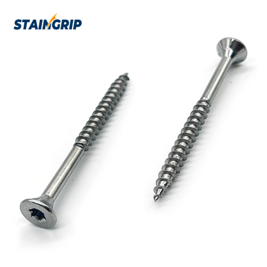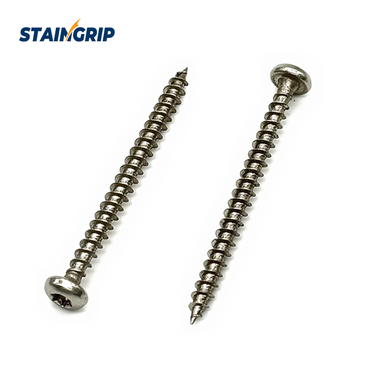
Confirm the drive system and size, then compare a known-good bit and an accepted screw with the suspect pair. Record insertion depth, movement and release before changing the recess.
Confirm the drive independently of the thread size
An M3 designation identifies a metric thread size; it does not specify the recess number. The head style and applicable drawing also matter. Six-lobed systems can look similar without being interchangeable at their intended load. The screw designation and bit manufacturer’s identification need to agree, including whether the system is conventional hexalobular or a proprietary variant. A bit entering the recess is not sufficient evidence of a correct working match. 1
The decking screw category includes designs with published Torx drives. Compare the Torx flat-head deck screw with the pan-head Torx wood screw as distinct head and application configurations. Confirm the specified drive size and finished drawing for each order; neither thread diameter nor the shared drive name establishes interchangeable bit engagement.
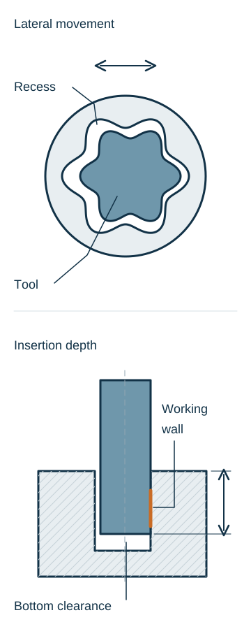
Check depth before judging sideways movement
Swipe the table sideways to compare every column. Keyboard: use the left and right arrow keys.
| Review item | What to check and how to interpret it |
|---|---|
| Next check | Once the drive system is confirmed, actual contact depth becomes the relevant question. |
| Tight feel at the mouth | A tool may feel tight because it contacts only the mouth of the recess. |
| Rocking before full insertion | It may also rock because it has not reached the useful sidewall contact region. |
| Possible obstructions | Coating buildup, debris, a damaged entrance or a mismatched tip are possible explanations for incomplete insertion. |
| Measurement and forcing limit | The specified inspection method provides a basis for comparing depth; forcing the bit deeper can damage the screw, tool or surrounding head material instead of establishing correct engagement. |
Inspect stainless screws in their delivered surface condition
The delivered surface provides evidence that a dimensional check alone may miss. An uncoated stainless screw can still carry forming residue, polishing compound or debris in its recess. Examination under suitable lighting helps distinguish these obstructions from an undersized profile. A passivated designation describes a surface-treatment requirement; it does not certify drive dimensions or prove that every recess is clear. When cleaning or polishing is proposed to improve fit, an untreated reference and measurements after treatment can reveal whether the process also changed the small contact features.
Clean inspection tools and trays help preserve the condition being investigated. Carbon steel particles introduced during handling can later rust on a stainless surface and complicate a drive-fit investigation. The functional check still needs a clean, correctly specified hardened driver; a soft improvised tool does not solve contamination control. Controlled handling addresses that risk, while dimensional fit and any later staining complaint remain separate questions.
Use a controlled cross-comparison
Swipe the table sideways to compare every column. Keyboard: use the left and right arrow keys.
| Review item | What to check and how to interpret it |
|---|---|
| Purpose | A controlled cross-comparison can separate tool effects from screw effects once the drive and surface condition are documented. |
| Controlled combinations | It combines a known-good new bit and the suspect bit with accepted screws and the suspect lot, using consistent bit types, handling and observation conditions. |
| Difficulty follows one bit | Difficulty that follows one bit across several lots directs attention to that tool. |
| Difficulty follows one lot | The same defect with several correct tools on one lot makes recess measurement a priority. |
| What the comparison cannot prove | This comparison narrows the search; it neither replaces dimensional acceptance nor proves a manufacturing cause by itself. |
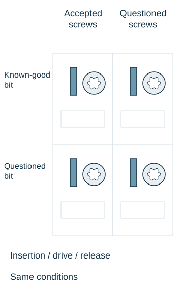
Example: interpret a loose-fit comparison matrix
A hypothetical stainless screw lot may feel loose with the bit currently used at an assembly station. An unworn reference bit of the specified system and an accepted screw sample create a useful comparison. The matrix records insertion depth, free movement and release for each bit with both screw lots. If only the used bit produces excessive movement, a change to the screw cavity would address the wrong variable. If both bits stop shallow in the suspect lot, the entrance and cavity become the next investigation targets before the tool program.
The matrix helps select the next measurement; it cannot turn a subjective feel into a numerical tolerance. Photographs of comparable engagement positions, linked to the bit identity and screw lot, allow the supplier to reproduce the observation and compare it with the specified gauge result. This evidence is more useful than a screw sent alone with an instruction to make its star socket tighter.
Measure the finished recess
The comparison identifies what to measure; acceptance still needs a defined measurement method. ISO 10664:2014 addresses hexalobular shape, basic dimensions and gauging for inspection. Its public scope explicitly distinguishes this from a manufacturing standard. A local diameter or visual judgment of straight sidewalls cannot describe the complete profile. The dimensional assessment needs to cover the specified contour and usable depth in the delivered surface condition. A punch adjustment should follow measured finished-part deviation; a blanket instruction to shrink the recess can create insertion interference elsewhere. 1
Swipe the table sideways to compare every column. Keyboard: use the left and right arrow keys.
| Review item | What to check and how to interpret it |
|---|---|
| Inspection identity | The supplier report should identify the inspection location within the recess, the gauge or method, the surface condition and the screw lot. |
| Passing reference | A passing reference is useful alongside the failed examples. |
| Reproducible measurement region | That combination makes the observation reproducible and helps prevent a later disagreement in which one party measures the mouth while another judges the working region. |
Use the quality and testing requirements discussion to agree the delivered-surface condition, recess dimensions and controlled bit or gauge reference for the selected screw. Product images do not define the inspection tolerance.
Confirm insertion, driving and release together
A correction must allow consistent insertion, torque transfer and removal under the intended assembly conditions. If static fit is acceptable but failures occur at production speed, examine alignment, feed timing, axial pressure and stopping behavior. Reduced hand wobble alone does not establish conformity. Record the agreed bit, inspection method and final finish so later batches use the same functional and dimensional acceptance basis.
Common questions
Can a production driver bit serve as the inspection gauge?
It can support an agreed functional check, but it does not automatically replace the specified gauge or measurement method. Tool wear, manufacturing tolerance and tip geometry influence its fit. A reference bit used in acceptance therefore needs its own identification and control, separate from normal production use.
Does a stainless grade explain why the bit feels loose?
Not by itself. Grade and processing can influence how a part forms and responds to load, but static fit is defined by the finished mating profiles and engagement. Measurements of those features provide the relevant starting evidence. A material change cannot substitute for identification of the correct drive system and control of its dimensions.
Reference Standards
These references describe standards and test methods within their stated scope. Listing a standard does not mean that a StainGrip product is certified to it or that a specific batch has passed a test.