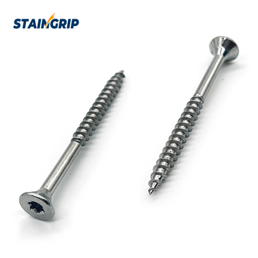
Start with the intended bit, available head space and required joint function. Define the critical finished dimensions and acceptance method before approving a sample or tooling change.
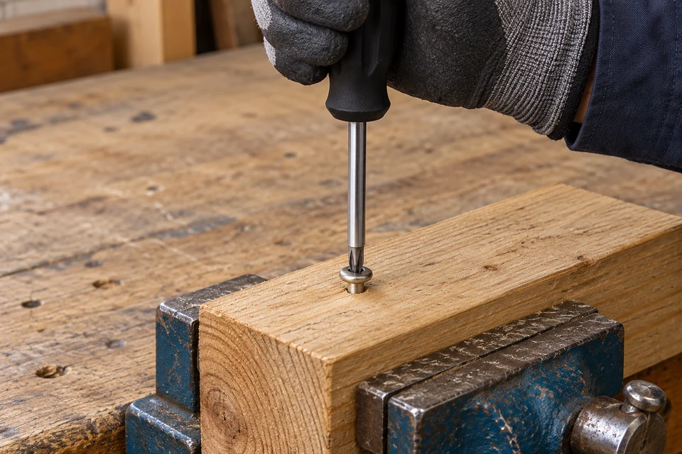
Identify the drive system before dimensioning it
Thread, head style and drive designation are separate entries in a complete specification. A metric thread size does not determine the bit size, and similar-looking six-lobed systems should not be treated as automatically equivalent. For a conventional hexalobular feature, ISO 10664:2014 addresses profile, basic dimensions and gauging. Its purpose is inspection rather than prescribing the manufacturing process. The product drawing must still resolve the features and conditions specific to your chosen screw. 1
The Torx flat-head deck screw provides a published example in which head style, drive and application must be specified together. Confirm the selected dimensions, material and final condition in the order; a product name alone does not define recess acceptance limits.
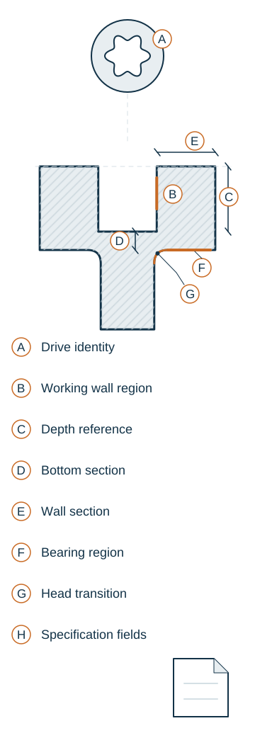
Define useful contact and remaining material together
Swipe the table sideways to compare every column. Keyboard: use the left and right arrow keys.
| Review item | What to check and how to interpret it |
|---|---|
| Working surfaces | The identified drive system defines the surfaces that must transmit torque. |
| Recess definition | Its recess requirements need an applicable standard or an agreed detailed drawing, including the relevant depth reference and inspection method. |
| Depth reference | A depth measured to the deepest central point is not automatically equivalent to usable sidewall engagement. |
| Surrounding section | A shallow head or unusual recess also makes the material remaining below and around the cavity important. |
| Coordinated tradeoff | Increasing depth can improve contact while reducing the section that supports the head, so the two requirements need coordinated evaluation. |
Include the bearing face and head transition
The drawing must also follow the load path beyond the recess. The underside of the head has a separate function from the drive recess. A complete definition includes the intended bearing region, relevant flatness or orientation requirements, transition fillet and clearance needed at the mating hole. A larger nominal head does not guarantee greater effective support. Bearing dimensions also influence the torque–preload relationship, so a supplier’s proposed head change should be reviewed with the assembly procedure rather than approved from top-view appearance alone.
Add material and finish fields for stainless screws
Swipe the table sideways to compare every column. Keyboard: use the left and right arrow keys.
| Review item | What to check and how to interpret it |
|---|---|
| Shape versus condition | These geometric requirements describe the shape; stainless material requirements describe the condition in which that shape must function. |
| Separate drawing entries | A stainless screw drawing should keep alloy identity, mechanical requirements and drive geometry as separate entries. |
| Incomplete grade descriptions | The terms 304, 316 or 410 do not define a recess tolerance, and an A2 or A4 designation is not itself a complete property class. |
| ISO 3506-1 applicability | Where ISO 3506-1 applies, its relevant material designation and mechanical requirements belong in the order; its scope does not supply a universal torque–clamp-force relationship. |
| Other screw families | Tapping, drilling and wood screws need their own applicable product requirements, because a metric machine-screw specification cannot be transferred without a scope check. 2 |
Any specified final cleaning, passivation, coating or lubrication condition also needs a clear record. This allows dimensional and functional acceptance to refer to the same delivered product. A visual appearance reference and dimensional gauges answer different questions: a bright stainless head may be attractive yet have the wrong contact geometry. Conversely, a functional recess can still fail an agreed cleanliness or surface requirement.
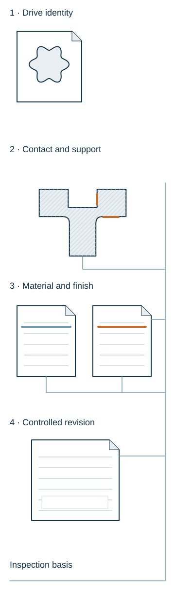
Agree on final-condition inspection and functional trials
Specify inspection after the relevant final treatment, using defined measurement references and tools. A satisfactory hand-fit sample does not establish a repeatable tolerance. Dimensional acceptance and an assembly trial answer complementary questions; neither replaces the other.
Swipe the table sideways to compare every column. Keyboard: use the left and right arrow keys.
| Record item | Fields to complete and limits |
|---|---|
| Drawing and reference sample | [Drawing revision; sample identity; head, drive and contact-depth requirements; material, mechanical and finish requirements]. |
| Final-condition inspection | [Final treatment before inspection; dimensions and tolerances; measurement references; designated bit or gauge; who supplies the reference; wear controls]. |
| Drive definition | [Applicable standard or authorized proprietary system definition]. A generic drawing and a different commercial bit do not define an equivalent proprietary system. |
| Functional trial setup | [Mating parts; tool program; axial support; acceptance observations]. |
| Working cycle and joint function | [Insertion; torque transfer; release; required joint function; acceptance criteria]. |
| Sampling, reporting and approval | [Sampling plan; dimensional and functional results; lot and report references; approved deviations and drawing revision]. A general drive standard does not supply a complete application-specific lot acceptance plan. |
The quality and testing requirements discussion provides a route to agree these final-condition checks for the selected screw. The resulting order-specific procedure, rather than the general page, defines acceptance.
Example: turn a sample-based inquiry into a repeatable order
A hypothetical buyer sends a stainless screw with the request same head, but less wobble. Before a tooling change can be evaluated, the reference features and the unsatisfactory feature need to be distinguished. The drive designation, head envelope, specified contact depth and intended bit give the supplier a basis for proposing a measurable revision and an inspection method. Keeping the approved drawing revision linked to the reference sample reduces the risk that a later buyer reorders the original, unsatisfactory geometry.
Complete the drawing and acceptance record for the revised sample so the next order uses the accepted geometry and controlled references.
Use the OEM screw and packaging requirements brief to communicate the head, drive, dimensions and critical tolerances together with the approved revision. Feasibility and verification remain subject to the actual specification.
Control changes by their finished result
When a supplier changes the preform, punch or material distribution, identify the finished feature being changed and how it will be verified. Compare trials under consistent conditions and inspect the complete head for new defects or dimensional conflicts. Keep the accepted result in the controlled drawing and inspection requirements; an undocumented request for a tighter or deeper recess cannot make it repeatable.
Common questions
Is an approved stainless sample enough for repeat orders?
A sample supports comparison, but measurable requirements and revision control make the order repeatable. Its preserved condition needs a clear link to the drawing, material condition, final finish and inspection method. Otherwise a later sample may look similar while differing at the tool-contact surfaces.
Should every visible dimension become a tight tolerance?
No. Features controlling tool fit, strength, seating and access deserve priority, while applicable product standards provide a basis for the remaining geometry. Unnecessary restrictions can increase manufacturing difficulty without improving the joint. A useful inspection plan explains how each critical feature supports the intended function.
Reference Standards
- ISO 10664:2014 — Hexalobular internal driving feature for bolts and screws
- ISO 3506-1:2020 — Stainless steel bolts, screws and studs
These references describe standards and test methods within their stated scope. Listing a standard does not mean that a StainGrip product is certified to it or that a specific batch has passed a test.